
Learn when gearbox backlash affects gear motor positioning, how to specify the test torque and measurement point, and when to address stiffness instead.
Gearbox backlash is the free angular movement caused by clearance between mating teeth. When torque reverses in a gear motor, the teeth move through that clearance before the opposite flanks carry the load. The effect matters most when a mechanism must settle at the same position after approaching from either direction.
Begin with the permitted error at the driven part. If it is a conveyor that normally stays loaded in one direction, noise, efficiency or gear life may govern the choice. If it is a reversing actuator with a long lever, a small angle at the gearbox output can consume much of the positioning tolerance.
Gearbox Backlash and Lost Motion
On reversal, the loaded tooth flanks separate and the gearbox crosses the clearance before the opposite flanks engage. A motor-shaft encoder may already register rotation while there is little or no corresponding movement at the output. Backlash describes that clearance-related motion; total reversal error can be larger.
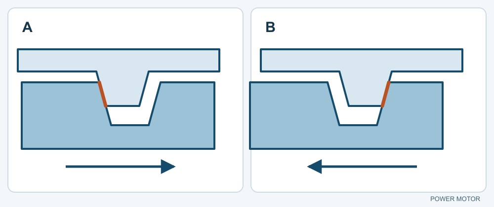
A controlled amount of operating clearance helps a gear pair accommodate manufacturing and operating variation:
- Lubrication. Tooth profile, surface speed, lubricant and temperature determine film behavior. Reducing clearance to a minimum without checking these conditions can increase friction and wear.
- Dimensional variation. Tooth thickness, center distance, runout and bearing fits affect actual clearance at different angular positions. Check the tolerance stack before setting a limit.
- Deflection under load. Gears, shafts and housings move under torque. That elastic motion adds to the apparent reversal travel under load, even when tooth clearance is small.
- Temperature and wear. Thermal growth can alter the running clearance, and wear or changes in preload can increase reversal motion over time. Check the expected temperature range and life stage.
For a production specification, state the maximum permitted value and where and how to measure it. A typical unloaded catalog value is not the same as a limit at operating torque or at the end of a durability test.
Backlash Lost Motion and Positioning Terms
Separate the clearance inside the gearbox from what the complete mechanism actually does under load.
| Term | Meaning in a gear motor system |
|---|---|
| Gear backlash | Free movement from clearance between opposite tooth flanks. State the shaft at which the angle is measured. |
| Lost motion | Reversal displacement under a defined test. Depending on the method, it can include both clearance and elastic effects. |
| Torsional compliance | Angular deflection per applied torque in the gearbox or other parts of the drivetrain. |
| Positioning error | Difference between commanded and measured load position under specified conditions. |
| Repeatability | Variation in measured position after repeated moves. State whether arrival is from one direction or both. |
Lost-motion measurements must be read with their test definition. Some suppliers quote a designated point on a torque-angle hysteresis curve; others report a broader reversal measurement. A gearbox with little tooth clearance can still twist under torque or move at a flexible mount. These effects show up differently depending on where the sensor is placed.
A preloaded or nominally zero-backlash gearbox can reduce free movement between flanks. It still has finite stiffness. It can also show transmission error as it rotates, so a zero-backlash label does not establish either absolute accuracy or bidirectional repeatability.
Applications Where Gear Backlash Matters
Start by asking whether the working load changes torque direction or approaches a target from both sides. A motor that rotates continuously can still cross its clearance during braking or if the load drives the output back.
The priorities below are typical starting points. The final tolerance belongs at the load, not at the catalog motor shaft.
| Application | Backlash priority | Why it matters | What to specify |
|---|---|---|---|
| Frequent reversals | Often high | Clearance is crossed when torque changes direction. | Output backlash, reversal rate, peak torque and wear. |
| Repeated stops at a target | Often high | Final position can shift with approach direction. | Bidirectional repeatability, settling time and feedback. |
| Robot joints and precision actuators | Set by error budget | Link length magnifies a small output angle. | Stiffness, backlash, arm length and load-side error. |
| Lab and medical equipment | Function dependent | A dosing or sample-handling axis may require repeatable travel. | Position tolerance, duty cycle and test load. |
| Automatic doors and lifts | Mechanism dependent | Clearance can affect reversal, noise and end behavior. | Torque, repeated cycles, obstruction and stopping tests. |
| Steady one-direction drives | Often lower | The same flanks carry load in steady operation. | Efficiency, temperature and noise; check braking reversals. |
Factors That Set the Backlash Limit
The same gearbox can be acceptable in one linkage and unsuitable in another. Check these conditions before assigning a limit:
- Load and torque. Specify both running and reversal torque. A small unloaded measurement does not predict angular deflection as the mechanism picks up a heavy load.
- Lever length. At a radius of 100 mm, a 0.2° angular reversal represents about 0.35 mm of tangential travel for a rigid lever. This is a geometry example, not a motor specification.
- Wear and life. A limit for a new assembly does not establish what happens after run-in, shock loads or durability cycling. Specify the life stage and include a post-cycle measurement where necessary.
- Encoder location. A motor-side sensor measures input motion. It cannot directly report tooth clearance or deflection downstream. An output-side encoder improves observability at the gearbox output; measurement at the driven part also captures linkage deflection.
- Position budget. Allocate the load-side tolerance across backlash, elastic deformation, sensor error and other relevant terms. Specify whether it applies from one approach direction or both.
A tighter gearbox can reduce reversal error, but it will not correct a flexible bracket or long linkage. Identify the largest measured contributor before paying to reduce the gearbox clearance.
Measuring and Reducing Gearbox Backlash
A useful comparison needs the same measurement boundary and test conditions. An angle measured on a bare gearbox with its input locked is not directly comparable to variation from a complete mechanism moving under load.
Request the following details with each quoted result:
- The angle measurement point and reference datum: input, output or driven load.
- Test torque in each direction, including the preload or zero convention.
- Units, angular positions tested and the range of recorded displacement.
- How the housing and input were restrained and whether the drive was powered.
- Temperature, lubrication state, mounting and assembly configuration.
- Sample condition: new, run-in, or after the specified durability cycles.
- Whether the result is typical, the largest measured value or a production limit.
- Whether couplings, external linkages and the final mounting are included.
An input-locked torque reversal at the output can reveal clearance and elastic motion under a stated load. As test torque rises, elastic twist contributes more to the measured angle. Harmonic Drive’s technical guide illustrates a torque-angle hysteresis method for its own gearing. Agree on how your supplier separates clearance from compliance before comparing values.
Mechanical Ways to Reduce Backlash
Select mechanical changes in response to the error you measured:
- Review tooth thickness, pitch deviation, runout and process capability.
- Control center distance, shaft alignment, bearing fits and housing stiffness.
- Tighten part or assembly tolerances where their contribution justifies the cost.
- Evaluate preload if the gear set and lubrication allow it.
- Compare gearbox architectures at matching loads and with the same test method.
- Stiffen shafts, couplings or mounts if the main issue is elastic deformation.
- Check shock and reversal torque separately from steady running torque.
Preload can reduce free movement at reversal by keeping tooth flanks engaged. It can also increase drag, heat and wear. Measure running current and temperature along with the resulting reversal error, including after cycling.
Feedback and Software Compensation
Decide where the system needs to know its position.
A motor encoder can improve speed or position control before the reduction stage. A sensor at the gearbox output measures what reaches that shaft but still misses any flex or free travel in the next linkage. For tight tolerances, compare position at the actual driven part with the command from both approach directions.
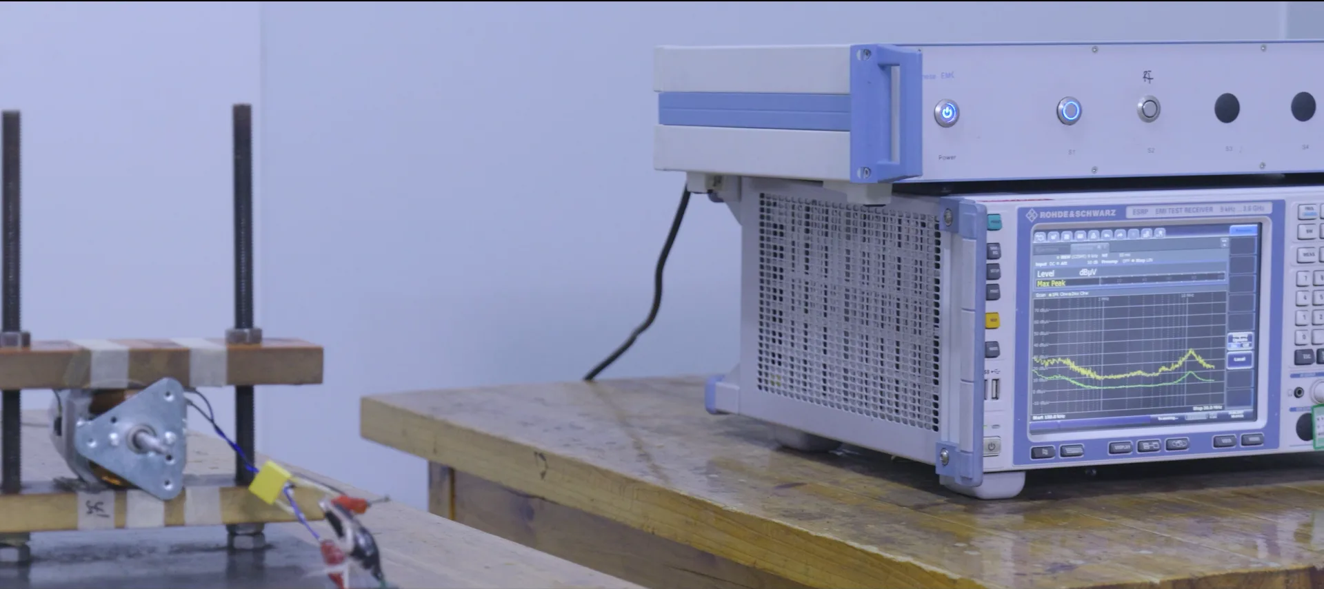
If the remaining reversal error is repeatable, evaluate one or more control measures:
- Apply an offset that is specific to approach direction.
- Use a measured compensation map if the error varies by travel position.
- Close the loop on the load position when the sensor and mechanics allow it.
- Recalibrate under defined conditions if temperature or wear changes the response.
- Approach critical points from the same direction if the travel path allows it.
- Check settling time after any correction rather than accepting the final reading alone.
An offset obtained on a new, lightly loaded gearbox may not work at a different torque or after wear changes the clearance. Validate compensation across the actual operating range; it cannot remove elastic deformation or repair worn components.
Report the before-and-after results at the load, alongside the test torque and direction. A lower quoted backlash value is valuable only if it improves the required motion or reduces variation in production.
Specifying a Custom Gear Motor With Power Motor
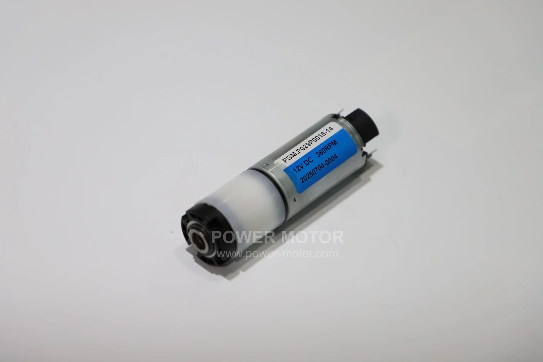
The Power Motor gear motor range provides motor and reduction-stage examples. Use the model drawings and performance data to check physical fit and the operating point. Request a separate reversal measurement if it is part of the requirement.
For initial sizing, see our gear motor selection guide. It explains how the reduction ratio and efficiency affect output speed and torque. Check the proposed gearbox’s continuous and peak ratings before applying those relationships in a design.
For an OEM project, agree on the elements included in the proposed drive:
- Motor platform and continuous operating point under the intended duty cycle.
- Gearbox architecture, torque rating and mounting configuration.
- Reduction ratio and the required speed at the gearbox output.
- Feedback type, location and minimum useful resolution.
- Controller interface, power supply and motion commands.
- Mechanical play, stiffness, noise and durability test boundaries.
- Output shaft, fixture, connector and envelope dimensions.
Send the following application data so the first comparison is based on your mechanism:
- Allowable error at the driven part and both approach directions.
- Reversal frequency, travel and permitted settling time.
- Continuous and peak output torque, including abnormal or shock loads.
- Target output speed and any motor-speed limits.
- Load inertia, lever radius and downstream linkage geometry.
- Expected duty cycle and planned durability validation.
- Mounting, interface and space drawings.
- Operating temperature, lubricant or contamination constraints.
- Feedback location, resolution and control interface.
- Sample quantity, production volume estimate and acceptance documentation.
Set the backlash limit after checking how much reversal travel the load actually permits. Where clearance is not the largest contributor, stiffer interfaces or better load-side measurement may deliver more improvement than a tighter gearbox.
For a gear motor assessment, contact Power Motor with the load drawing, motion profile and proposed acceptance test.