
Compare Hall sensor and sensorless BLDC control for loaded starts, low-speed operation and restart. See three controller examples and an OEM test checklist.
Evaluate Hall feedback first if the motor must start against a load, reverse frequently or run at low speed where back electromotive force (back EMF) is weak. Evaluate sensorless control if the machine spends most of its duty cycle at a stable speed and the drive can start the actual load reliably. That distinction affects the motor controller, wiring and validation work.
Define the worst operating conditions before comparing the two. A motor that starts on a bench may fail with a cold gearbox, a loaded pump or an impeller already turning. Set limits for start time, peak current, unwanted movement and minimum stable speed, then test both approaches against the same limits.
How Hall and Sensorless Drives Determine Rotor Position
A brushless DC motor uses electronic commutation. To produce torque in the intended direction, the drive needs the rotor position or an estimate of it. Hall sensors report the rotor’s magnetic position directly; a sensorless drive estimates it from signals at the motor terminals.
Hall Feedback
A common arrangement uses three digital Hall sensors. Their combined states identify the rotor’s electrical sector, including at standstill. The drive can use that initial state to select which phases to energize. The Hall state does not tell the drive the exact angle within the sector.
At zero speed, a valid Hall state gives the drive an initial commutation reference. It does not prove that the motor can start a given load. Use it as a starting point when the equipment must:
- Overcome breakaway friction without an unintended reverse movement.
- Run at its specified minimum speed under load.
- Restart repeatedly within a defined time and current limit.
- Reverse without excessive peak current, shock or mechanical play.
- Develop adequate starting torque at the lowest expected supply voltage.
- Handle load changes without stalling or exceeding temperature limits.
In a conventional six-step arrangement, the Hall state changes every 60 electrical degrees. The rotor completes one electrical cycle per pole pair in each mechanical revolution. If the motion problem is precise positioning rather than commutation, specify the required feedback resolution separately. See the Texas Instruments Hall commutation application brief.
Sensorless Estimation
A sensorless drive estimates rotor position without a Hall sensor or encoder on the motor. It still needs measurements from the drive, and its performance depends on the estimation method and the motor.
A common six-step implementation detects back electromotive force (back EMF). Rotor motion induces voltage in the windings, and that voltage increases with speed. The drive uses a measured electrical event to time the next change in phase excitation.
In classic sensorless six-step commutation, the drive energizes two phases and monitors the floating phase. It detects a back-EMF zero crossing against a suitable reference and uses it to schedule the next commutation. Switching noise and the decay of phase current can make the measurement unreliable if sampling is poorly timed.
Different sensorless drives may use the following measurements or functions. They serve different roles; having one does not establish the minimum usable speed:
- Phase current measured at a defined point in the PWM cycle.
- Terminal-voltage measurements or estimates of phase voltage.
- Back-EMF estimation rather than direct zero-crossing detection.
- Rotor position and speed observers based on a motor model.
- A phase-locked loop to track estimated electrical angle.
- An estimator used with field-oriented control (FOC).
- Motor parameters and temperature effects accounted for in tuning.
Back EMF is zero at standstill and small at low speed, so a drive that relies on it cannot identify the initial rotor position from that signal alone. Some sensorless designs use a different initial position method; check what the proposed hardware and firmware actually support.
One common startup sequence aligns the rotor, accelerates it in open loop and switches to estimation once the signal is usable. A loaded start can fail at either stage. For a fan that may be windmilling, test restart in both observed spin directions rather than relying on the stopped-rotor test.
Rotor Feedback and Current Control
Specify two items independently when reviewing a controller:
- Rotor feedback: Hall signals, an encoder or a sensorless estimate.
- Drive method: for example, six-step commutation, sinusoidal drive or field-oriented current control.
Hall feedback is often used with six-step commutation. Some drives use Hall transitions to estimate an angle for sinusoidal control. Sensorless drive can likewise use six-step zero-crossing detection or an observer in an FOC system.
An FOC label alone says nothing about how the drive starts at zero speed or maintains stable low-speed torque. Ask which feedback is available before the shaft moves, how the control method changes as speed rises and what happens if the estimate becomes unreliable.
Hall and Sensorless BLDC Comparison
Use this table to decide what to evaluate first. Compare the motor, controller, harness and load as one system under the same supply, temperature and installation conditions.
| Selection factor | Hall feedback | Sensorless control |
|---|---|---|
| Loaded startup | An initial rotor sector is available at rest. Confirm starting torque and current. | Back-EMF drives need a separate startup sequence. Validate it with the actual load. |
| Minimum stable speed | Useful when back EMF is weak. Check ripple and the feedback resolution required. | Depends on estimator and motor. Basic back-EMF sensing has a low-speed limit. |
| Medium and high speed | Check Hall timing and the drive’s electrical-frequency limit. | A candidate when the signal is strong across the working range; verify the upper limit. |
| Sensors and wiring | Adds motor-side sensing, harness conductors and connector pins. | Can reduce feedback wiring. Phase sensing and filtering are still needed. |
| Drive development | Direct sector input can simplify initial commutation. | Estimator, startup and transition behavior may require more calibration. |
| System cost | Include the sensors, harness and assembly cost. | Include sensing, firmware tuning, validation and service costs. |
| EMI and signal quality | Check Hall supply, signal integrity, harness routing and connector faults. | Check switching noise, sampling timing and estimator sensitivity. |
| Fault handling | Define behavior for invalid states and missing or intermittent signals. | Detect failed starts, loss of synchronism and recovery limits. |
| Environment | Qualify sensors and their harness for the operating temperature and vibration. | Removes those sensor parts. The drive and motor still require environmental validation. |
| Where to evaluate first | Loaded starts, frequent reversals and low-speed motion. | Fans and blowers with mostly steady running and validated starts. |
An actuator may need to move immediately against static friction. Hall feedback is a practical candidate when the maximum permitted start time or reverse travel is tight. The result still depends on the available current, commutation timing and required breakaway torque.
With a blower that usually runs at steady speed, the motor can often generate a usable signal across most of its duty cycle. Removing Hall leads may simplify the harness and connector. Test startup with the production impeller and inlet conditions before committing to the architecture.
A Hall design adds sensors and signal wiring; a sensorless design shifts more work to sensing and firmware. Compare the cost of the full drive, validation and service. Noise should be measured in the assembled equipment because the impeller, housing and mounting can dominate the result.
Hall Startup and Sensorless Running
A hybrid design can use Hall feedback during startup and switch to sensorless estimation after reaching a defined operating region. It retains the Hall hardware. The reason to adopt it should be a measurable requirement in the running mode, not the assumption that changing methods improves performance.
Validate the handover at the actual supply and load limits. Record torque or speed disturbance at the transition. Confirm the behavior if the load pulls the motor back below the usable estimation range, and check how firmware detects and recovers from loss of synchronization.
Control Selection by Application
Use the actual motion and load envelope to choose a first candidate. For the controller examples, the published maximum speeds apply at the stated pole-pair counts. For the same shaft speed, a motor with more pole pairs requires a higher electrical frequency.
| Application | Common operating priorities | First control option to evaluate |
|---|---|---|
| Linear and compact actuators | Breakaway torque, low speed, reverse travel and settling. | Hall feedback. Add finer feedback if positioning accuracy requires it. |
| Automatic doors | Repeated starts, reversals and obstruction behavior. | Hall or a validated hybrid drive; verify the full mechanism’s response. |
| Medical equipment | Speed ripple, acoustic limits, fault response and EMC. | Choose by function. Confirm both low-speed control and device-level evidence. |
| Variable-load pumps | Starting pressure, changing load and stall recovery. | Hall or sensorless drive tested across the load envelope. |
| High-speed blowers | Impeller load, temperature, speed range and restart. | Sensorless if loaded startup and restart are repeatable. |
| Hair dryers | Impeller, air path, input supply and acoustic targets. | Sensorless for suitable designs. Verify the assembled airflow system. |
| Fans | Minimum speed, repeated starts and restart while coasting. | Sensorless or Hall depending on startup and low-speed targets. |
| Vacuum cleaners | Changing air restriction, battery or mains supply, and thermal limits. | Compare under matched load, including restart and restriction cases. |
A useful prototype test measures the intended load, not just free rotation. Use the production mechanism, impeller or a representative load, and reproduce both normal and difficult starts.
Ask the following questions before approving the control architecture:
- What breakaway torque is needed at minimum supply voltage and the coldest start?
- What inertia does the drive see at the motor shaft, and how fast must it accelerate?
- What is the lowest stable loaded speed, and what ripple is acceptable?
- How often will the motor start, brake or reverse? Can it be turning when restarted?
- Which load changes or obstructions may stall the motor during normal use?
- What connector, current rating, cable length and routing can the design accommodate?
- What noise and vibration limits apply when installed in the final housing?
- Which electromagnetic compatibility tests apply to the complete equipment?
- What should the equipment do on stall, undervoltage, overcurrent or loss of position feedback?
- How many repeated starts and duty cycles must pass, and how will failures be recorded?
For example, compare start time, failed starts and peak current for a fan after a short power interruption. For an actuator, measure travel in the commanded direction at the tightest load point and the lowest usable speed. Those are different validation conditions even if the motors use similar drives.
Matching a BLDC Motor and Controller at Power Motor
In a motor and controller development review, start with the load and its interfaces. Rated speed and torque do not establish a viable pairing if the drive cannot supply starting current, use the available feedback signals or meet the project’s electrical-frequency limit.
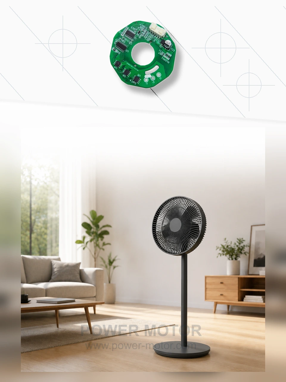
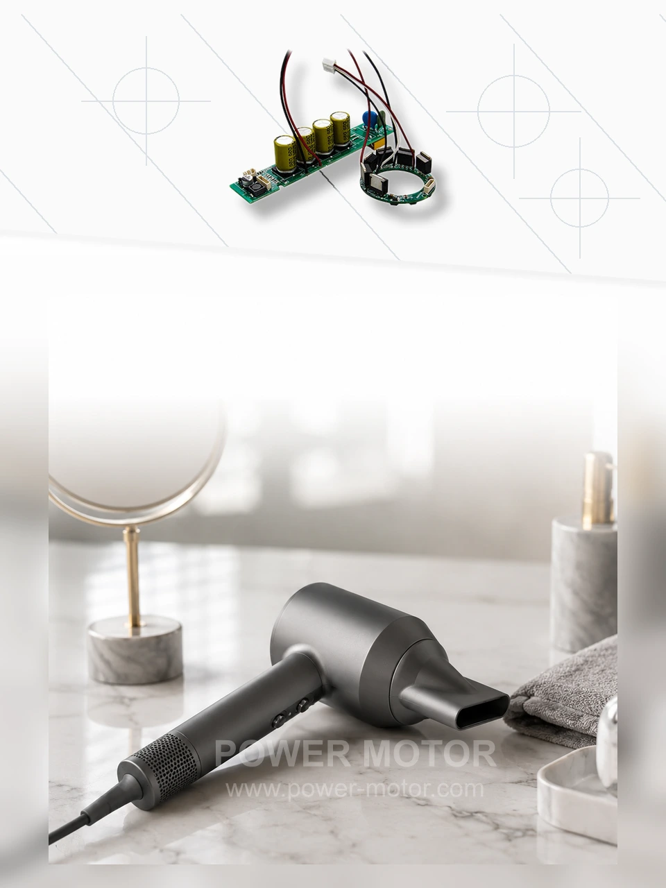
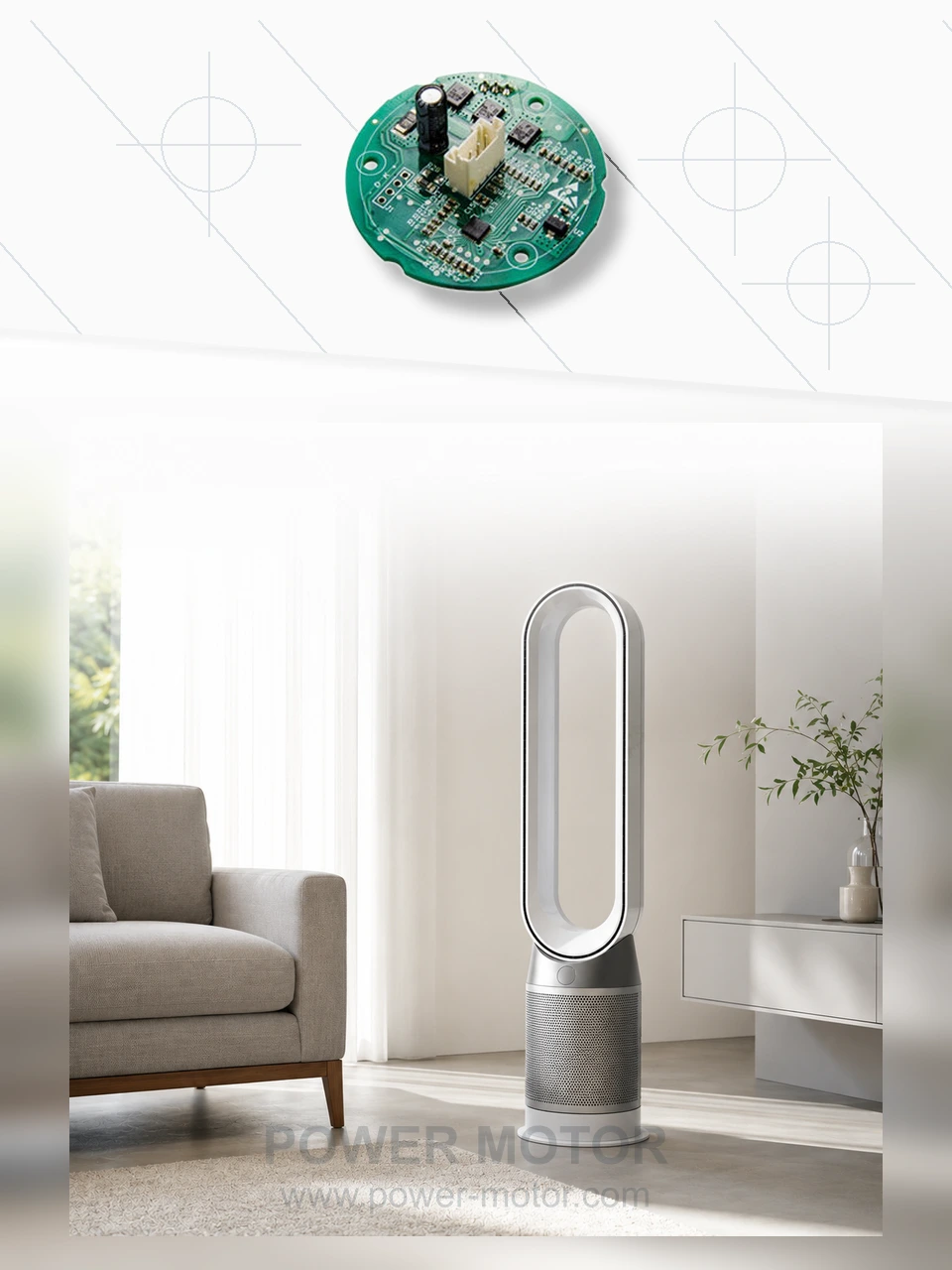
Our motor controller range includes sensored and sensorless approaches. The three published boards above are examples of different control choices. Compare each board’s supply, feedback method and motor pole count before treating it as a candidate for your equipment.
To review a motor and drive together, send these project inputs:
- Continuous and peak torque at the required shaft speeds.
- Breakaway torque, inertia and the permitted start time.
- Minimum, normal and maximum speed under load.
- Drive input supply range, current limit and supply transients.
- Mounting envelope, shaft interface, connector and harness layout.
- Duty cycle, cooling conditions and service-life target.
- Acoustic limits, EMC requirements and the intended fault response.
- Start, stop, brake and reverse commands, including restart conditions.
Agree on the test fixture and acceptance limits before comparing samples. A controller’s catalog speed does not substitute for a test at the application’s continuous operating point. Check the winding temperature, available torque and drive current at that point.
Selection and Prototype Approval
Put the decision in terms of the failure that matters most. A loaded actuator can miss a movement because startup torque is insufficient or because the controller cannot identify the rotor position. A steady-running fan has a different risk: it may run normally after a clean start but fail to recover while windmilling.
Evaluate Hall feedback for the actuator if standstill position information is needed. For the fan, consider sensorless control if it passes the full startup and restart envelope. Where the decision remains open, compare both on the same motor, load and acceptance criteria where feasible.
For a custom BLDC motor and drive assessment, contact Power Motor with your torque-speed requirements, intended supply, startup conditions, duty cycle and mechanical drawing.