
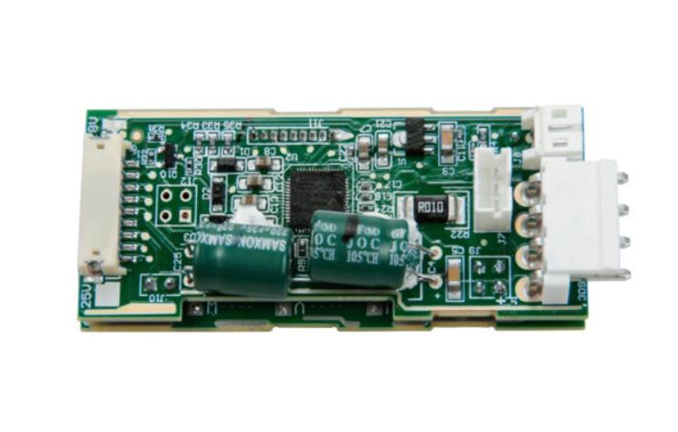
Choose a motor controller by motor type, supply range, continuous and peak current, feedback interface and required motion functions. A brushed DC H-bridge, a BLDC inverter and a stepper driver are not interchangeable. The controller must match the motor and the load, not just share its nominal voltage.
Match the power stage to the motor
| Motor | Required drive function |
| Brushed DC | Control armature current/voltage; use a suitable reversing power stage where needed |
| BLDC | Provide sequenced multi-phase currents with compatible commutation |
| Stepper | Regulate winding currents and accept supported positioning commands |
| AC universal | Use a drive designed for the specified AC/DC motor and supply |
Specify more than a peak current number
Check the continuous current under the actual cooling conditions and the allowed peak duration. Battery/input current and motor phase current are different quantities in a switched drive. Ask which current a specification describes. Include startup, acceleration, obstruction detection and the expected stop method in the requirements.
Encoder and Hall feedback checklist
An encoder can report motion or position, while Hall signals often provide commutation information. Their functions and interfaces depend on the chosen system. Confirm feedback supply voltage, signal type, pinout, resolution and controller support. A quadrature interface, serial encoder and analog sensor are not interchangeable merely because they use a similar connector.
- Use the exact motor, encoder and drive connection diagrams; wire colors are not a universal pinout.
- Identify motor phases separately from feedback power, signal returns, protective earth and cable shields.
- Confirm logic levels, differential or single-ended signaling and shielding requirements.
- Check the required commutation alignment or commissioning procedure before loaded operation.
- Verify that reported direction, speed and position agree with measured motion.
Low-voltage supply does not define the motor phases
A BLDC drive may accept a single DC supply but deliver a three-phase switched output to the motor. The supply description therefore does not tell you the motor winding connection. Similarly, a low-power command from a microcontroller is a control signal; it does not replace the motor power stage.
Validate the complete system
Test at the supply extremes and representative loads. Record startup current, speed regulation and temperature. Verify controller behavior for feedback loss, blocked motion and supply interruption. During braking, identify whether energy is dissipated, returned to a supply that can absorb it, or handled by another documented means.
Brushed DC speed-control guide
Technical reference
Texas Instruments: sensored BLDC control and feedback interfaces