
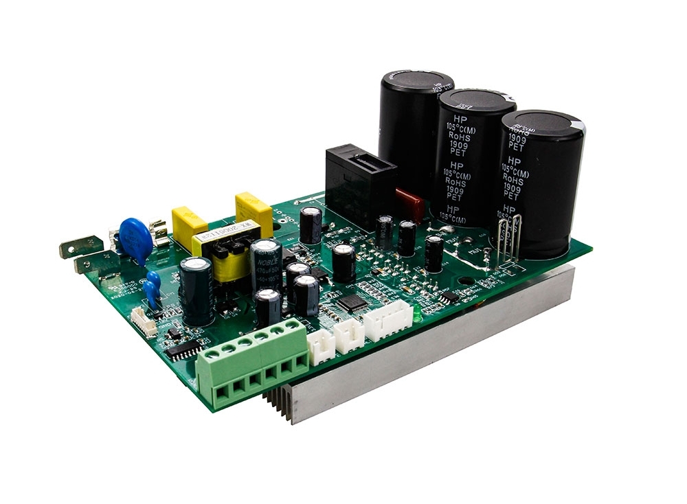
For a permanent-magnet brushed DC motor, speed is commonly controlled with a suitable PWM power stage. Add speed feedback when the speed must stay close to its target as the load changes. A BLDC motor needs a compatible commutating drive; its speed command is not interchangeable with direct PWM switching of a two-wire brushed motor.
Voltage, current and speed
For a simplified steady-state PMDC model, V = I × R + kE × ω. V is motor terminal voltage, I is armature current, R is winding resistance, kE is the back-EMF constant and ω is angular speed. This approximation omits switching transients and brush drop. Increasing load usually requires more current; at a fixed supply, the resulting voltage drop can reduce speed.
Choose the control method
| Method | Useful role | Limit |
| PWM power stage | Efficiently adjust the applied voltage for a suitable brushed motor | Duty cycle alone does not guarantee a fixed loaded speed |
| Closed-loop speed control | Use encoder or other speed feedback to correct speed error | Needs compatible feedback, tuning and current limits |
| Series resistance | Simple demonstrations or specific legacy circuits | Dissipates heat and produces load-dependent speed |
| Field-current control | Certain wound-field motors with an accessible field winding | Not a general method for permanent-magnet brushed motors |
PWM duty cycle is not a speed specification
A higher duty cycle generally increases the available average applied voltage, but load torque, winding resistance, switching behavior and supply limits determine the result. Select PWM frequency using the drive and motor requirements. Verify winding-current ripple, switching losses, audible noise and electromagnetic compatibility rather than assuming one frequency suits every motor.
Commissioning checklist
- Record the minimum and maximum supply voltage under load.
- Set current limiting from the motor and drive ratings before increasing speed.
- Check loaded startup, minimum stable speed and acceleration.
- Observe winding or case temperature over the intended duty cycle.
- Verify reversal and braking using the documented power-stage behavior.
- Test a feedback fault and a jammed mechanism using the product’s defined protective procedure.
When speed drops under load
Measure supply voltage at the drive, current, actual shaft speed and temperature. Separate a weak supply from controller current limiting or a mechanical overload. Increasing voltage to conceal overload can exceed motor or drive limits. A different ratio, larger motor or revised acceleration profile may be more appropriate.