
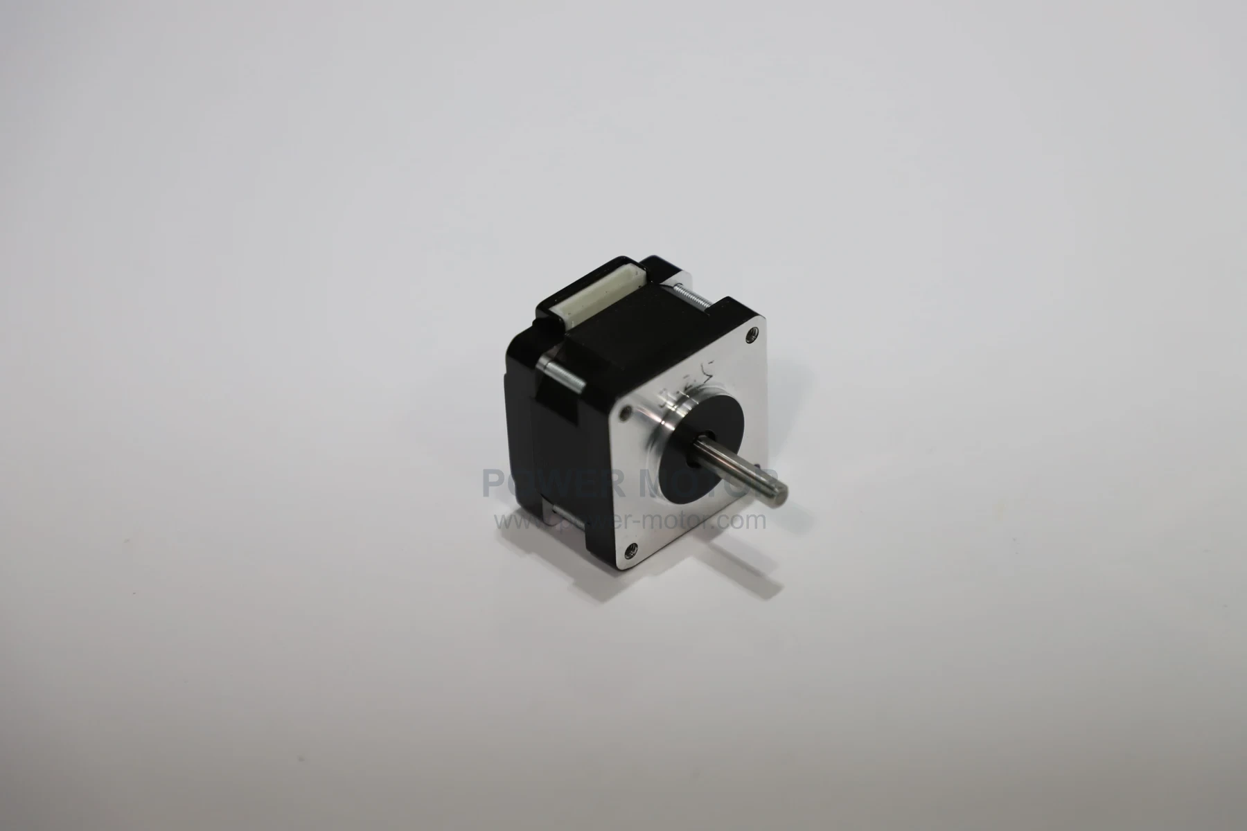
Review stepper motor operation, construction, drive methods and selection limits. Step angle is not the same as complete-system positioning accuracy.
A stepper motor is an open-loop control motor that converts electrical pulse signals into precise angular or linear displacement. For each input pulse, the motor rotates by a fixed angle (known as the step angle) in the preset direction. Since its displacement is directly proportional to the number of pulses and its speed is proportional to the pulse frequency, it achieves precise positioning without requiring position sensors, making it a crucial component in automation control systems.
I. Core Working Principles
The operation of a stepper motor is based on a fundamental physical principle: the principle of least magnetic reluctance, which states that magnetic fields always prefer to follow paths of minimal resistance. Its core components include a stator—a permanent magnet or magnetic material rotor with multiple toothed surfaces, and electromagnets with toothed surfaces. The windings are arranged according to phase numbers (e.g., two-phase, three-phase, five-phase).
For stepper positioning, review PST.39HB in the current catalogue. The catalogue lists printers and stage lighting. Step angle is not system positioning accuracy; validate the load, transmission and drive settings separately.
Brief description of the working process of the stepper motor:
1. The controller sends a pulse current to a specific phase (or several phases) of the motor's windings, exciting the winding to generate a magnetic field.
2. The rotor teeth will actively align with the stator teeth under the action of magnetic field to achieve the state of minimum magnetic reluctance.
3. The controller switches the energized state of different windings in a predetermined sequence (i.e., "excitation sequence"), causing the stator's magnetic field axis to rotate stepwise.
4. The rotor will follow the stator's magnetic field step by step to keep the magnetic circuit minimal.
5. The sequence of pulses determines the steering direction, the frequency of pulses determines the rotational speed, and the number of pulses determines the total rotation angle.
II. Main Types and Characteristics
1. Permanent magnet stepper motor with a rotor made of permanent magnetic material. Key features include a large step angle (e.g., 7.5°,15°) and low torque, but it retains torque after power loss (self-locking). The design is simple and cost-effective. It is suitable for applications requiring low precision and torque, such as basic printing devices and instrument pointer drives.
2. Reactive stepper motor features a rotor made of soft magnetic material without permanent magnets. Its key characteristics include a high number of rotor teeth, a small step angle (as small as 1.8° or even smaller), and a high torque. However, it lacks holding torque when power is cut off, resulting in relatively high power consumption. This type of motor is now rarely used and is commonly found in older equipment.
3. Hybrid stepper motor, combining permanent magnet and reaction-type rotors. The rotor integrates both permanent magnets and toothed slots, combining the advantages of both types. It features a small step angle (most commonly 1.8° and 0.9°), high torque, smooth operation, and precision. This type is the absolute mainstream in modern industrial applications, widely used in CNC machine tools, 3D printers, robots, precision instruments, and automated production lines.
III. Key to Drive and Control System
The performance of the stepping motor depends on the driving system. The core of the driver is to convert the weak current pulse from the controller into the strong current needed by the motor winding.
1. Excitation and microstepping: subdividing the commanded step can reduce certain motion disturbances and increase command resolution. It does not make command resolution equal to positioning accuracy; load, detent torque, current regulation and mechanics still affect the result.
2. Drive Technology: Modern stepper drives typically include: a pulse/direction interface for receiving commands from PLCs, microcontrollers, or motion control cards; a current control circuit employing constant-current chopping technology to enhance efficiency and torque output; a microstepping control circuit; and protection features such as overcurrent, overheating, and short-circuit protection.
Ⅳ. Strengths and Limitations
superiority :
1.Open-loop control with a simple system: It achieves precise positioning without expensive encoders, thus reducing costs.
2.Control intuitively: position, speed and pulse number, frequency directly correspond, easy to program.
Exceptional low-speed torque: Maintains rated torque at low speeds (including zero speed), ideal for direct load driving.
3.Zero cumulative error: Each step's error is completely isolated, ensuring high positioning accuracy.
4.Wide speed range: The wide speed range can be achieved by changing the pulse frequency.
5.The structure is robust and easy to maintain.
boundedness :
1. Missed steps and resonance: load inertia, acceleration and operating speed can affect stepper motion. Driver settings, damping and mechanical design may reduce these effects, but positioning performance still requires testing under the intended motion profile.
2.Relatively low efficiency: The winding remains energized regardless of load status, resulting in heat generation.
3.High-speed torque drop: The output torque drops sharply as the rotational speed increases.
4.Potential risks of open-loop control: If the system loses synchronization, it cannot detect the error, resulting in positional inaccuracies.
V. Typical application areas
1. Additive manufacturing: The 3D printer's X/Y/Z-axis positioning enables precise control of the extruder and printing platform.
2. Office automation: paper feeding and scanning head movement for printers, scanners, and copiers.
3. Industrial automation: CNC machine tool feed axis, cable cutting machine, dispensing machine, automatic assembly line, robot joint (lightweight).
4. Medical equipment: infusion pump, ventilator, and sample arm drive of analytical instruments.
5. Security and optics: PTZ cameras, microscope autofocus, telescope positioning.
Contact Us Today:
For a motor selection enquiry related to this article, share the application, supply, load, duty cycle and installation requirements through our contact page.
Note: This article is contributed by Power Motor Sales Department